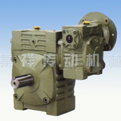
| Size | Input (Kw) |
Ratio | A | AB | BB | BE | AC | BC | AD | BD | HL | LL | H | Z×L | Flange | Input hole | Output shaft | ||||||||
| LA | LB | LC | LE | LZ | Q | U | T×V | LS | S | W×Y | |||||||||||||||
| 40-70 | 0.2 |
1/200 1/300 1/400 1/500 1/600 1/800 1/900 |
287 | 126 | 131 | 75 | 152 | 86 | 125 | 65 | 200 | 90 | 215 | M10×25 | 115 | 95 | 140 | 4 | M8 | 31 | 11 | 4×12.8 | 60 | 28 | 8×4 |
| 50-80 | 0.18 | 314 | 144 | 142 | 83 | 169 | 102 | 140 | 70 | 235 | 105 | 250 | M12×28 | 115 | 95 | 140 | 4 | M8 | 31 | 11 | 4×12.8 | 65 | 32 | 10×5 | |
| 60-100 | 0.37 | 387 | 175 | 169 | 91 | 216 | 117 | 180 | 90 | 290 | 130 | 310 | M12×30 | 130 | 110 | 160 | 4 | M8 | 33 | 14 | 5×16.3 | 75 | 38 | 10×5 | |
| 70-120 | 0.37 | 425 | 193 | 190 | 109 | 256 | 124 | 220 | 100 | 345 | 155 | 370 | M14×32 | 130 | 110 | 160 | 4 | M8 | 40 | 14 | 5×16.3 | 85 | 45 | 14×5.5 | |
| 0.75 | 445 | 111 | 165 | 130 | 200 | M10 | 42 | 19 | 6×21.8 | ||||||||||||||||
| 80-135 | 0.75 | 499 | 226 | 210 | 125 | 296 | 147 | 260 | 110 | 400 | 185 | 425 | M16×35 | 165 | 130 | 200 | 4.5 | M10 | 48 | 19 | 6×21.8 | 95 | 55 | 16×6 | |
| 1.5 | 52 | 24 | 8×27.3 | ||||||||||||||||||||||
| 100-155 | 1.5 | 570 | 269 | 252 | 148 | 345 | 185 | 280 | 120 | 458 | 203 | 461 | M16×35 | 165 | 130 | 200 | 4.5 | M10 | 52 | 24 | 8×27.3 | 110 | 60 | 18×7 | |
| 120-175 | 2.2 | 631 | 287 | 262 | 181 | 374 | 192 | 320 | 140 | 518 | 223 | 521 | M16×35 | 215 | 180 | 250 | 5 | M12 | 63 | 28 | 8×31.3 | 110 | 65 | 18×7 | |
| 3.0 | |||||||||||||||||||||||||
| 135-200 | 3.0 | 680 | 318 | 305 | 202 | 412 | 230 | 360 | 150 | 580 | 245 | 575 | M20×36 | 215 | 180 | 250 | 5 | M12 | 63 | 28 | 8×31.3 | 125 | 70 | 20×7.5 | |
| 4.0 | |||||||||||||||||||||||||
| 155-250 | 5.5 | 815 | 380 | 360 | 247 | 500 | 285 | 420 | 190 | 705 | 300 | 700 | M24×42 | 265 | 230 | 300 | 5 | M12 | 83 | 38 | 10×41.3 | 155 | 90 | 25×9 | |
 Print
Print
 Top
Top
 Close
Close